
NCU test jig is developed to test DI and DO of the NCU hardware. Testing can be done “Automated” using some piece of software loaded in Test jig or can be done “manually” by operator. Test jig is capable of turning ON 16 channels of any supplied voltage (0-48VDC) independently. Any of the 16 channels can be switched ON/OFF manually as well using momentary switch by operator or through loaded software, these channels are used as Digital input (Alarm input) for NCU hardware under test.
Key features
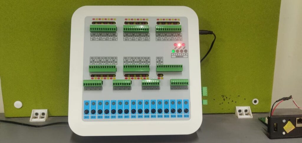
- 5V-3A Adaptor with 5.5mm OD and 2.1mm ID barrel jack used to supply Test jig. With LED indication for healthy supply.
- Separate connector to provide DI voltage (0-48VDC) pulse to NCU under test which will be independent and isolated from test jig supply. Separate LED indication for DI voltage availability.
- Ethernet Connectivity 4. UART Interface which can either be TTL or 232 Level. (Can be configured only once).
- Four software configurable Debug LEDs & one heartbeat LED. 6. Separate LED indications for up to 42 NCU DO contacts and 16 NCU DI.
- Raspberry Pi 4B used as main controller with four I2C IO expander for DI/DO.
- Linux based system with Hardware Drivers so that Application code can be changed depending upon the device under test